Abstract
In this project our team programmed a Kuka robotic arm to track and shoot a dart at a flying quadrotor UAV. This was achieved by using task space control to position a customized rocket-launching end effector at the position and orientation that will intersect the path of the quadrotor. An off-the-shelf USB dart launcher was hacked with custom hardware to interface with an Arduino microcontroller. The quadrotor firmware was modified to allow autonomous position control with motion capture data transmitted by custom ground-station software.
Demonstration
The video below shows the kuka and the autonomous quadrotor running our code.
The next video below is using a toy RC helicopter for a smaller, faster target.
Methods
We used an existing C++ Kuka API to send our desired commands the robot running ROS. The control methodology was based in task-space, as opposed to joint-space.
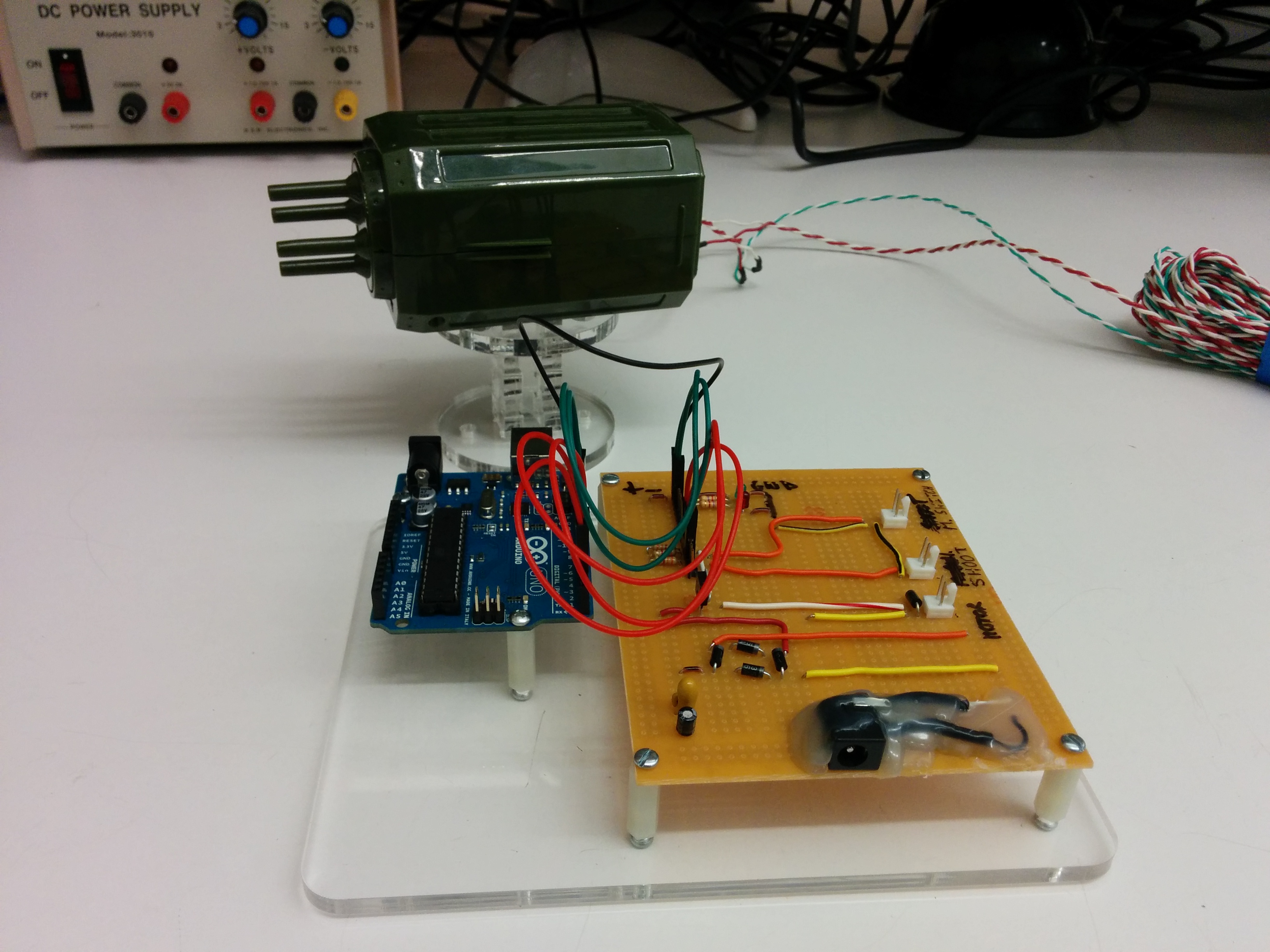
A USB foam rocket launcher was modified to be controlled with an arduino and a user input button as opposed to the supplied proprietary software.

We estimated the dynamics of the darts as they are launched by using the optitrack system to record their trajectories. A simple windowed average was used to smooth calculated velocity from the position data. An average launch velocity of 9m/s was found.
Since the Kuka client does not allow joint torque control, we cannot apply repulsive fields to avoid joint limits or singularities. One possible solution explored was to apply a task-space controller with repuslive fields to a simulated robot. The resulting joint angles from the simulation would be sent as command values to the Kuka through our client. However we were concerned that this simulation-in-the-loop control could lead to instabilitiy and would rely heavily on data speeds. Instead, we decided to limit our end effector workspace to a virtual box to avoid joint limits and singularties.
Optimal Trajectory Prediction
In order to account for the motion of the target, an optimizer was written to satisfy the the vector equation:
Where q denotes quadrotor position and velocity, ee denotes end-effector position, Vdart represents the launch velocity of the dart, bearing denotes the unit vector parallel to the launch velocity, g is the gravitational acceleration vector (adjusted to compensate for lift during flight), and tf is the time of flight of the dart.
Solving this system of equations yields three remaining degrees of freedom. Our apporach was to optimize over this nullspace using an objective function that will balance spatial movement of the end effector, rotation of the end-effector frame, and shortest time of flight:
Using IPOPT numerical nonlinear optimizer with full objective gradient, constraint Jacobian, and primal/dual Hessian information, the optimizer was able to consistently solve within acceptable tolerances in 4 milliseconds. The optimizer was shown to work under simulation conditions with this control frequency. However, during testing on the actual Kuka robot, the 250Hz control frequency produced stepped motion at a much lower frequency (below 20Hz) which made the controller useless in practice. It seems that the Kuka software performs agressive downsampling and filtering on incoming commands. The visible stuttering of the Kuka robot only disappeared when commands were issued at greater than 5kHz.
Autonomizing the Quadrotor
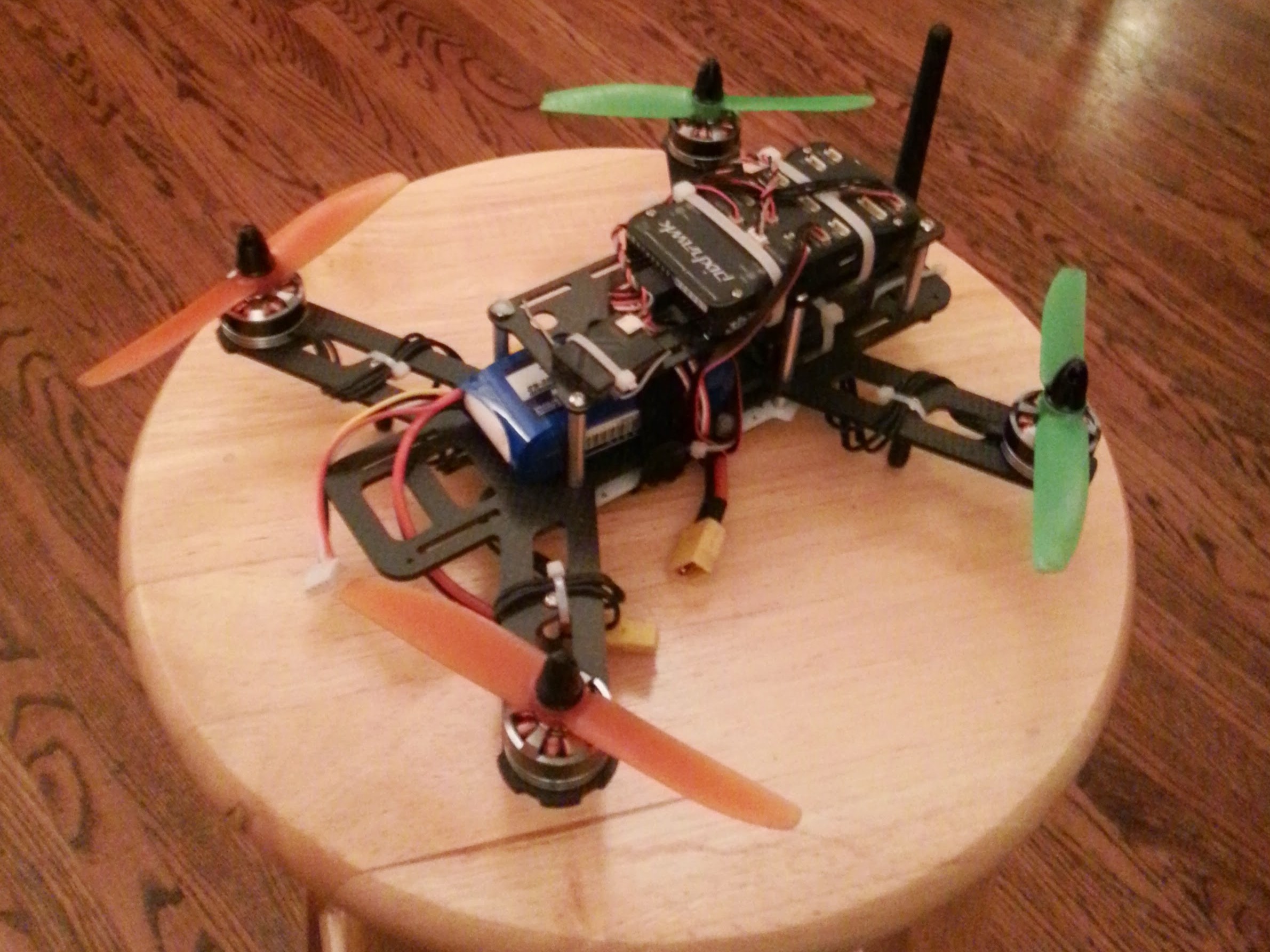
Due to the constrained space in the robotics lab, we wanted to modify the autopilot software to be able to autonomously hold position. To accomplish this we needed to provide the spatial position of the quadrotor because there is no GPS signal, and also a replacement for the magnetic field readings because the metal structures and electrical current significantly warp the magnetic field in the lab. The position is easily found through a constant homogenous transform matrix, and the magnetic field reading is found by the x-axis column vector of the body rotation matrix assuming the global X-axis is North.
In order to communicate this information to the quadrotor, a program was written that sends Mavlink messages through a radio transmitter. A message with 6 floating point variables corresponding to the North-East-Down position, and the global North vector represented in current body-frame coordinates was sent to the quadrotor at 25Hz. Onboard the quadrotor, the autopilot was reflashed with a custom version of the firmware. We disabled all magnetometer output by modifying the drivers so that only the fake magnetometer data will be used. The Mavlink message receiver module was modified to recieve this new message and update the data structures for position and magnetometer measurements accordingly.
Finally, with the data being correctly recieved, the estimators required tuning to match the new fake sensors. The attitude estimator is an Extended Kalman Filter. The element in the observation covariance matrix corresponding to the magnetometer was isolated and adjusted to match the improved certainty of the fake sensor. The position estimator is a simple linear inertial filter. The gains were increased for the position measurement corrections until the estimator response was very slightly underdamped with overshoot of around 10%. Real time filtered attitude and position data were plotted from the quadrotor to validate the tuning and ensure the performance was satisfactory.
The quadrotor was successfully flown in the lab as seen in the videos below. There is room for improvement in perfromance of the position controller that could be gained by fine-tuining the position PID gains, and adding another low-latency sensor such as an optical flow device. Additionally, the case when the motion capture system loses track of the quadrotor (flies too high, or out of the area) was not yet handled, and would result in loss of position control stability in most cases. During our final demo for the course we chose not to fly the autonomous quadrotor because of this possible edge case resulting in injury to a spectator.
Authors and Contributors
This project was completed as a part of Stanford's CS225a Experimental Robotics, Fall Quarter 2014
The team members are:
*Guilia Guidi (M.S. Mechanical Engineering)
*Joel Pazhayampallil (M.S. Mechanical Engineering)
*Kyle Reinke (M.S. Aero/Astro Engineering)
*Sagar Saxena (M.S. Mechanical Engineering).
Contact
Please refer to the Team Members side bar above to access our LinkedIn profiles. Thank you!
This page was generated by GitHub Pages using the Architect theme by Jason Long.
